Better Edge Determination for Rotary Encoders
September 14, 2013

A standard edge sensing scheme for optical rotary encoders is to square up the raw analog sine wave by comparing it against a given voltage. If your analog signal has a 2Vpp amplitude, the value at which you switch off of, creating the edges of your square waves, could be around one Volt. This would put the determination point right in the middle of the analog signal and provide symmetrical high and low pulse times.
An example of this can be seen below. The Blue sin wave is the raw analog signal from the sensor, the red line is the DC voltage which it is compared against. You can see at that the crossing points of the red and blue lines are the points at which the edges of the square waves are determined. The Magenta waveform is the digital output of the optical encoder.
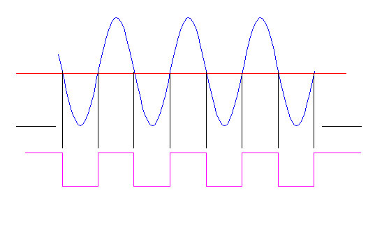
But what happens if the analog signal amplitude changes? Raw signal amplitude does vary over time, temperature, and rotational speed. Below is an example of the raw analog amplitude of a signal changing to twice the normal value.
Note that the frequency of the signal hasn’t changed. Frequency is determined by the optical encoders rotation speed.
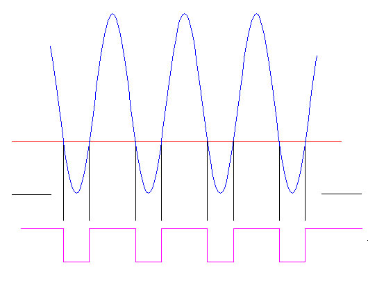
We see that the Red line is at the same voltage level, which it would be, as a resistor divider, or Zener diode often sets this value, but the edge determination points have changed as the red line is now cutting though the sine wave at a position that is lower relative to the rest of the waveform. As you can see by the magenta digital output, this creates asymmetric high and low pulse times.
This is real positional error that will vary with time, temperature and speed.
Quantum Devices Inc. patented sensing technology combats this by using two sets of analog signals for each channel and comparing them against each other.
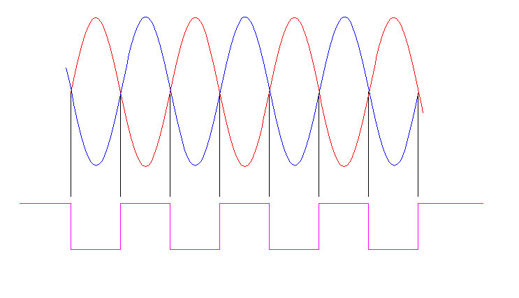
Instead of using a fixed voltage as the comparing signal, a complementary sine wave is used. The QDI interlaced sensor provides another sine wave that is a perfect match and exactly 180 degrees out of phase with the original. This complementary signal is shown in Red. The standard analog signal as shown in Blue.
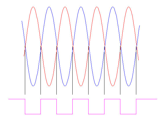
When we look at a doubling in amplitude under this scenario, the advantage of making edge-determining decisions at the crossing points of the signal becomes clear. No matter how much the amplitude changes, the complementary signal changes to match, maintaining perfect symmetry of the encoder signal.

