E-mail on Creating a Post Quad Encoder Signal
August 13, 2013
Below is an e-mail response I sent to someone who was asking about how to calculate the sampling rate they needed to 4X encoder signals. 4Xing or “Post Quad” is a way to use the fundamental A and B encoder pulses to get a higher line count.
I wasn’t sure if he was under the assumption that by sampling at a 4X rate he could essentially get 4X the signal, so I felt a long winded reply was needed.
The blue bulleted lines are his original questions.
Hi Stan,
I didn’t see it in this e-mail train, but I understand that your are looking to get 80,000 counts from the 20,000 line count encoder.
Here is my take on your questions which I have highlighted in Blue:
- One rotation per second would give me 20kHz from each phase (A&B)
This is correct.
- In a perfect world, I would need to sample the phases at 4 times this rate
- But there is a 10% tolerance on phase to phase, so I need to increase this rate by a factor of 1/.9 or a total 4.4 times the phase frequency
You must be going after the 2X rule as it applies to anti-aliasing, then since there are two channels multiplying that by two. Then, I see that you are also adjusting for phase shift.
Your math appears to be right on track, but I am going to go into detail here with some pictures as it is easier for me to communicate my meaning this way. Besides, I was in AutoCad anyway…
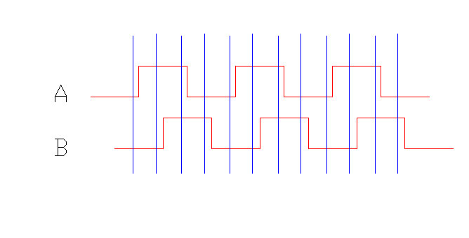
Below is a pictorial representation of sampling at 4X the fundamental frequency of A (or B) . The blue lines are sampling points and the red square waves are the A&B waveforms. The thickness of the blue line may not be appropriate as sampling will take a certain amount of time, so the lines could potentially be thicker, but the idea will be the same.
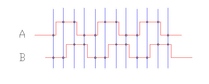
The points at which the blue lines cross the red square waves will define the high and low points, in the photo below they are circled.

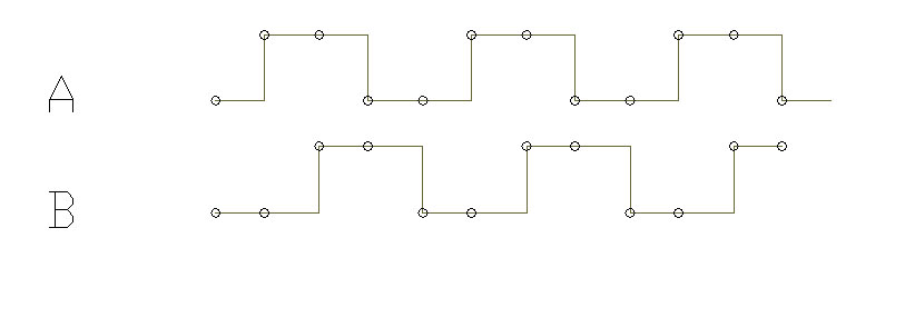
Removing the blue and red lines indicates the data points as seen by the computer/sampling device.

Then connecting the dots….

We see that this sampling rate essentially correctly “maps” the waveform, introducing some phase shift error. Depending on where sampling occurs this error may be as high as just under 90 electrical degrees, but does not directly give you 4X the frequency.
You may already be aware of all of this and are just asking “How low of a sampling frequency can I get away with ?” My answer would be 4X will be more than enough, as 2X the max frequency on each channel is all that is really necessary. Even the extra amount you added for phase shift may not be necessary, as any phase shift does not change the underlying frequency.
I just wanted to make sure that it was clear that sampling at 4X the rate is not the same as 4Xing the signal.
In practice 4Xing the fundamental signal is usually done by applying some sort of one shot or monostable circuits that are triggered off of the rising and falling edges on both channel A and Channel B, then using an AND logic gate to combine the two into one signal.
The duration of this pulse will be constant regardless of speed, as it is programmed into the one shot, but the “low time” between pulses will vary with rotational speed.
This is the hardware way to do it, it and sounds like you may be approaching it via software.
Let me know if you have any other questions,
Jim

