Interfacing to 26C31 Line Drivers in QDI Rotary Encoders
March 2, 2013
Encoder Electrical Structure
The internal electrical structure of the QDI series of encoders consists of a photo interrupted light source that is picked up by a common mode photo detector array.
“Common mode” means that there are two channels that are at exact opposite states in any position. The advantage of common mode sensing is that light and noise interference does not create false triggering, but is instead filtered out.
Besides having common mode signals, the incremental channels are also set up in an interlaced fashion. High-resolution channels need to be interlaced to provide a greater amount of signal strength and noise immunity at analog levels. An advantage of Quantum Devices’ patented phased array sensor is that all active areas receive the same amount of light, eliminating the need to balance signals with an encoder potentiometer.
At this point, the signals from the sensor are at small analog voltage levels. Depending upon the line count of the encoder these analog voltage levels may or may not be amplified before being digitized by a comparator.
The purpose of the comparator is to “square off” the signals to create digital signals. The comparator converts these Digital signals into single ended (Referenced to ground) signals. Besides being single ended, these digital signals are still not robust enough to be used directly by most applications.
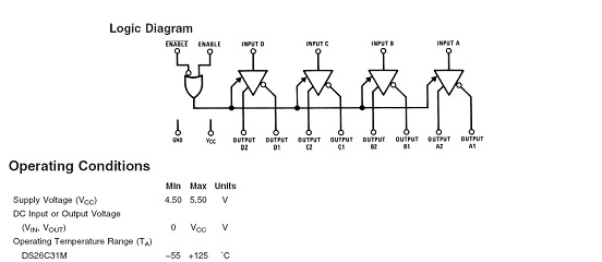
After the comparator, the signals are sent to a Line Driver. The line driver splits each signal back into two complementary signals, and also provides the ability to deliver much more current.
The output of the line driver is then electrically connected to flying leads or an interface connector of the encoder, making it the final interface device inside the encoder that is electrically connected to the outside world
Damage to the line driver can occur if the amount of power the line driver is delivering is greater than its specification. The amount of power is directly related to the resistive, inductive, or capacitive loading of the line driver.
DS26C31 Output Schematic

Areas of Concern that may Contribute to Line Driver Failures
If the flying leads of the encoder are shorted to other leads or if the leads are shorted to the supply voltage, or ground. Excessive current may be allowed to flow through the output channel of the line driver. This current generates heat that the IC is not able to dissipate and damages the internal junction. This junction may fail open or closed effectively creating a locked Hi or Lo Electrically. Proper termination of both used and unused leads before power is applied to the encoder is essential to prevent unintentional shorting.
If the output channels of the encoder are loaded too heavily (greater than 100 ohms) then the Line Driver IC may not be able to dissipate the heat from the internal junction and can damage the line driver.
If the encoder is operated in ambient temperature exceeding specifications there is a possibility for damage to the encoder outputs as the difference between the encoder temperature and the ambient temperature plays a key role in the ability for the Line driver to dissipate heat. If there are any uncertainties as to the environment that the encoder is to be used in QDI engineering should be consulted for recommendations.
External Voltage that is applied to the outputs of the encoder may cause damage. This can come into play if a line driver is set up to be used in an open collector style application and pulled up to a voltage higher than VCC. You can recognize this situation if you are using a pull up resistor with a power supply that is something other than the power supply for the encoder. A pull up resistor is typically more effectively used with an open collector type output, where as line driver outputs should be terminated to signal ground or to complementary signals in a differential fashion.
Interfacing to a line driver output with a power supply different than the encoders. Using a separate isolated supply to pull up an output or to interface to the encoder can cause signal amplitude irregularities, noise problems and line driver failure. The signal ground for the encoder should be electrically tied to the power supply common of any systems that are interfacing to the encoder.
Explore our optical encoder wiring guidelines or reach out to our engineering staff with questions.

