Ladder Logic to Decode Direction from an Optical Encoder
April 15, 2014
I set up a QR145 optical encoder on a Direct Logic DL06 PLC with some simple Ladder Logic to determine direction based on the A and B incremental inputs.
Below is a video of the optical encoder in action:
In the PLC I used (DL06), the inputs are filtered, which makes the response time very slow and limits the RPM that can be read. Please note that you will always need to take into account the maximum input frequency of your PLC when interfacing to an encoder.
Also, please note that this code was set up for demonstration/learning purposes only and has not been tested in a field application.
The first two rungs of ladder logic are used to lock direction after it has been determined from the optical encoder.

Inputs X0 and X1 are the respective A and B signals from the QR145 optical encoder.
Outputs C0 and C1 are used to latch direction, which is determined by the next high pulse after both signals go low (Latch C4) .
Rung three is used to latch when both channels are low. This is a penultimate point in that the first signal to go high after this latch is set tells us the direction of the encoder.
Rungs four and five drop out the current direction latch when a direction change occurs.


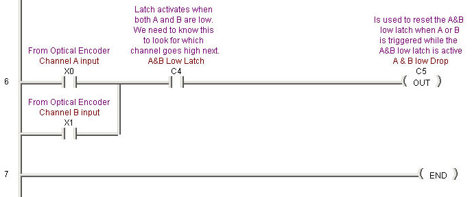
Rung six is used to reset the low latch. If we don’t have this, the program will permanently latch into the first direction is sees.


