Optical Encoder Incremental Signal Measurement
March 26, 2014
While most of us are familiar with how to measure something in mechanical degrees, incremental encoder signals are measured in electrical degrees.
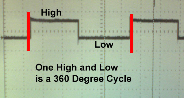
360 electrical degrees is the period in which a signal completes one high to low transition. This can be in any sort of waveform, but for encoders electrical degrees are usually used when referring to digital signals.

Why Measure in Electrical Degrees?
We measure Incremental Optical Encoder signals in electrical degrees because this gives us a number that is not depended on other information. If you were to talk about the high time of your encoder signal being 10 milliseconds, it doesn’t say anything about the quality of the signal unless you also talk about total cycle time.
An electrical degree specification gives us information about the signal with just one number.
Incremental Optical Encoder Symmetry
The ideal output for an incremental channel is a waveform with a 50/50 duty cycle. This specification is termed “symmetry” and called out in electrical degrees. Ideal symmetry is one where the high and low times of a channel are each 180 electrical degrees.
Some oscilloscopes will have a way to measure electrical degrees directly by setting a full cycle to 360 degrees. In this post I am going to assume that your scope doesn’t have that feature and calculate electrical degree symmetry measurements using the high, low and cycle durations as measured in time.

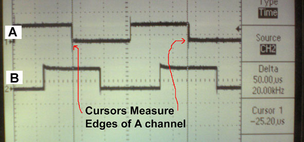
In the photo above the duration of a full cycle is 50.00 uS.

In this next photo, we adjust the cursors to check the High time of the A channel we see that it is 24.80 uS
To find what this time would be in electrical degrees, we calculate as:
(high time/ cycle time) *360
Or
(24.80 uS/50.00 uS)* 360 = 178.56 Electrical Degrees
To find the low time you could measure it and again repeat the calculation (substituting in low time for high time, but as long as the high time measurement was done carefully it is just as easy to subtract the high time from 360 Electrical Degrees to get the low time in Electrical Degrees.
360 – High pulse in electrical degrees = Low pulse in Electrical Degrees
Or
360 – 178.56 = 181.44 Electrical Degrees
Note that to get the most accurate measurement you will want to widen out the cycle as far as possible.
Channel B is measured in the same way.
Incremental Optical Encoder Minimum Edge Separation
Minimum A to B edge separation is an important measurement as the more time you have between the edges, the easier it is for a drive or controller to “see” the data coming in. This is particularly true with older equipment and when running at high speed.

Ideal A to B edge separation is 90 electrical degrees. To find edge separation in an incremental optical encoder look for the smallest separation between adjacent edges of all six edges within an overlapping set of A & B cycles.
To change from time to electrical degrees, we use a calculation similar to the one used for symmetry.
(Smallest Measurement/cycle time) *360 = Minimum Edge Separation in Electrical Degrees.
or
(12.00 uS/ 50.00 uS) * 360 = 86.4 Electrical Degrees Minimum A to B edge Separation
Video of an Incremental Optical Encoder being Tested for Symmetry and Minimum Edge Separation
For Optical Encoders with excellent symmetry and edge separation go to Quantum Devices’ encoder page
Quantum Devices Inc. is a leading manufacturer of optical rotary encoders. Visit our encoder store or contact us online with any questions.


