Optical Encoder Pulse Counting with a PLC
April 19, 2014
I have interfaced a QR145 200 Line Count Optical Encoder to a DL06 PLC and set up the PLC for mode 20 ‘High speed Up/Down counter’.
Here is a video of Optical Encoder Counting:
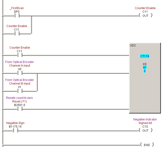
Below is the ladder logic code for programming the PLC to count pulses from the QR145 optical encoder using high speed counting mode. Note that “high speed” for the DL06 standard inputs is still limited to 7kHz where the encoder can go as high as 500 kHz by specification.
Setting up the ladder logic code for the DL06 is fairly straightforward in that the UDC (up down counter) seems to be built to take optical encoder inputs.
When in high speed mode, inputs X0 and X1 are inputs to the counter (CT174) by default. Input X2 is a reset input and could be wired to the index channel on the optical encoder if we were looking to translate the count into a 360 Position, but is left unwired for this up down count application.

The first rung on the counter (CT174) is the ENABLE. I latched C11 off of the first scan bit (SP0) to enable the counter. Note that CT174 was not picked arbitrarily, it is the specified counter location for high speed counting
The use of X0 and X1 on the second rung of the counter may seem a bit odd if you thought they were feeding counts to the counter. Instead, those inputs are being used to update the count from the input buffer to the counter memory location. To ensure that we always have the most accurate information, I place the two inputs parallel to trigger the update whenever we see a pulse from A OR B. This rung could also be held on for constant updating.
I am using bit 2501.0 (the F1 Key from the panel) to force a reset on the counter whenever the button is pressed.
Bit 1175.15 is the MSB from counter CT174 and indicates when the count has gone negative.
For more information on Optical Encoders check out the Quantum Devices Inc web page.


