Optical Encoder Waveform Triggering
July 28, 2014
Seeing Encoder Quadrature with a Two-Channel Scope
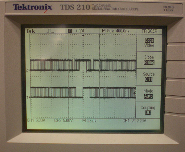
I received an e-mail from a customer concerned about the “out of control” optical encoder signals he was seeing on his Oscilloscope.
The photo below shows the type of signal he was seeing:

The encoder in question was a 10,000 Line Count optical encoder. I noticed that he was running relatively slowly, about 100 RPM. At that speed, a lot of BLDC motors will show some degree of motor cogging, which is irregularity in rotation due to the magnetic fields in the rotor.
The customer was also triggering on an incremental channel (A&B) and not the index (Z) channel.
I am sure he had omitted the index as he wanted to see if the A&B incremental encoder signals were in quadrature.
I knew that when triggering on an incremental channel, the oscilloscope triggers off of whichever ever edge happens to occur within the scopes timing window. What the customer was seeing on the oscilloscope was overlapping screen shots of the incremental channels as the motor speed changed.
In other words, he was seeing the encoder report exactly what the motor was doing.
If the customer were to trigger on Optical Encoder channel Z (Index) with one scope channel, they could see a nice steady signal. If they wanted to check quadrature, they could then compare the phasing of A and then the phasing of B relative to where the index channel was located.


That’s a little bit of a hassle, it’s much nicer to see both A and B optical encoder signals on the scope at the same time. The way to do this with a two-channel scope like the Tektronix TDS 210 we have, is to use the scope’s external trigger and trigger off of channel Z.
The video below compares the optical encoder signals being triggered off of channel A and then being triggered off of channel Z.
Jim is an Applications Engineer for the leading optical encoder manufacturer Quantum Devices Inc.


