What is an incremental encoder?
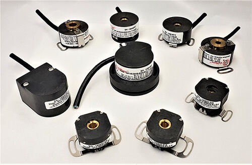
An incremental encoder is an electromechanical device that measures changes in motion and direction. Incremental rotary encoders generate A/B digital output signals based on a specific number of pulses per rotation. In this way, the angular motion of a shaft is converted into a code (encoded) to determine its velocity or relative position. Because incremental encoders give near instantaneous feedback on position changes, they’re often used in applications where highly precise measurement and motion control is required, such as robotics.
On this page:
It’s important to note that incremental encoders can only report information about position change. To calculate absolute position, the incremental encoder signals must have an interface, an electronic circuit that receives, processes and communicates encoder signals to outside circuitry such as a controller or counter. Changes in position are then measured in reference to a fixed “home” location, which must be established each time the encoder is turned on or reset.
How do incremental encoders work?
Incremental encoders generate a fixed number of pulses during one rotation. The number of pulses per revolution (PPR) defines an incremental encoder’s resolution, or how precise its measurements are.
The pulses are emitted as digital output signals using two incremental channels (A and B). If you only need to know speed (RPM) but not direction, only the A channel is used. When you need to know both speed and direction, channels A and B are used together.
The A and B channels have a phasing offset of 90 electrical degrees. This is called quadrature because there are 360 electrical degrees in one pulse encoder cycle. When the A and B signals are in quadrature at a constant speed, the digital output consists of two square waveforms with a 90-degree phase difference.

When the shaft spins in the opposite direction, the relationship between the A and B channels reverses. In this way, incremental encoders can provide rotational directional data.
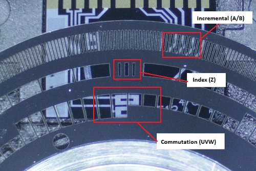
Incremental encoders also generate a digital signal called an index pulse which outputs data once per revolution on a dedicated channel (Z channel). The index pulse is commonly used to verify the pulse count of the A and B signals, or to track the number of shaft rotations with a counter. The index pulse can also be used for homing (determining absolute position) by starting the Z output signal with the shaft in a reference orientation. The width of the index pulse can be gated (restricted) to improve accuracy.


Incremental encoders can also have commutation channels (U, V, W) which are timed to the commutation channels of a BLDC motor. The commutation channels signal to the controller when current is needed for the motor windings which in turn generates motion. Quantum Devices manufactures incremental encoders with built-in commutation signals that easily align to a servo motor’s commutation channels.

Encoder disc with labels for incremental, index & commutation channels.
What are incremental encoders used for?
Incremental encoders can be used in a wide range of applications. Most often they’re used in conjunction with motion controls to track and direct the position of mechanical devices like medical equipment, AGVs, machine tools, and many other types of equipment that use an electric motor.

Quantum Devices manufactures high-performing incremental optical encoders well suited to many different industrial applications. Our engineers can also create a custom configuration for your specific application.
What’s the difference between an incremental and absolute encoder?
An incremental encoder is different from an absolute encoder in the type of information it measures. Incremental encoders measure change in position. Absolute encoders report the absolute position, which is a designated starting point.
Because the absolute or zero position of the shaft is recorded, an absolute encoder is always able to provide position data – even after a power failure, or if the shaft moves while the encoder is turned off. In contrast, an incremental encoder requires a reset or reference position every time it’s turned on in order to determine its position in rotation.
Incremental encoder specifications
Every incremental encoder manufactured by Quantum Devices has electrical, environmental and mechanical specifications.
Electrical specifications:
- Input voltage
- Input current requirements
- Input ripple
- Output circuits
- Incremental output format
- Max. operating frequency
- Commutation format
- Commutation accuracy
- Interpolation factors
Environmental specifications:
- Storage temperature
- Operating temperature
- IP rating
- Humidity
- Vibration
- Shock
Mechanical specifications:
- Bore minimum diameter
- Recommended shaft tolerance
- Minimum shaft engagement
- Allowable shaft runout
- Allowable axial shaft movement
- Mounting
- Dynamic commutation adjustment range
- Moment of inertia
Explore our incremental optical rotary encoder products and select any model to see its specifications, or download our incremental encoder line card.
What are the components of an incremental encoder?
Because incremental encoders don’t provide an absolute position, the internal components are relatively simple.
A typical incremental optical encoder assembly includes:
- Light source (LED)
- Interrupter disc with translucent and opaque sections
- Photodiode (optical sensor)
- PCB (printed circuit board)
- Solid or hollow shaft
- Housing

Light from the LED passes through openings in the metal disc onto a photodiode sensor. Each light pulse is converted into an electrical pulse by the photodiode, which is connected to a PCB. The signals are then transmitted to a user interface.
Not all incremental encoders are created equal. Quantum Devices’ encoders are made with a patented interlaced photodiode specifically designed for translating light into electrical current.

LED mounted in PCB of incremental encoder (seen from above and beneath).
Our products include many important differences in component quality and design that result in easier installation, more reliable signal quality and a longer service life. Unlike many encoder manufacturers, Quantum Devices designs and produces all encoder components in-house for better supply chain and quality control. See this modular optical encoder comparison for more detail.
Incremental encoder resources
Quantum Devices engineers have published several articles on different aspects of incremental encoders:
- Incremental encoder signals explained
- Incremental encoder signal measurement
- Finding the index pulse
- Finding the index pulse using a DMM
- Incremental encoder index pulse gating
- High-resolution incremental encoders
- Picking the resolution of an incremental encoder
- How to calculate incremental encoder pulses per degree
- How to calculate RPM from encoder pulses
- How to calculate output frequency for incremental encoders
- How to use an incremental encoder to measure angles
- Reducing electrical noise in incremental encoders
- Interlaced sensor technology in incremental encoders
- Incremental encoders for automated guided vehicles
- Building an incremental encoder quick tester
- Incremental encoder design using potentiometers
- Gray code for incremental encoders
- Cable length considerations for incremental encoders
If you have questions about incremental encoders or would like to request a custom configuration, please don’t hesitate to contact us. Free encoder samples are available for qualified projects.
Incremental Encoder Sales & Support
Since 1989, Quantum Devices has been known for incremental encoder manufacturing innovation. Our high-performance encoders are used in a wide variety of motion control applications. You can buy incremental encoders online direct from our store or find a distributor.
To find out which encoder model would be best for your specific application, or to request a custom configuration, contact Quantum Devices today.

