How to Time Optical Encoder Commutation Channels to a BLDC Motor
March 17, 2014
Optical Encoder Brushless DC Motor Timing Using Back EMF

The optical encoders we work with have a set of three Commutation tracks (U,V,W) which correspond to the three phases of the motor (R,S,T).
Alignment of the optical encoder commutation signals to a BLDC motor could be thought of as being comparable to timing the distributor of an auto engine. Just as the distributor tells the spark plugs when to fire, the optical encoder tells the amplifier/drive when to fire the windings in the BLDC motor.
And just like a car engine, if the timing alignment is off, the motor will not run correctly, will run inefficiently, or will not run not at all.
If two phases are accidentally reversed, the motor may even run backwards.
Keep in mind that you will need to have the information that describes which motor winding corresponds to which encoder commutation signal before trying to align an optical encoder to a BLDC motor.
Basic Steps:
1) One phase of the motor is energized locking the motor into position.
2) The encoder is rotated to a given position, which is usually the start of one of the commutation signals (I.E. leading edge of U). Often times this corresponds with the encoders index pulse.
3) The encoder is assembled to the motor and the shaft is locked in place (via encoder set screws). The encoder flex mount is not yet secured.
4) The motor winding is de-energized.
5) The optical encoder is powered.
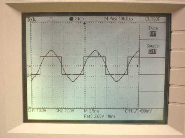
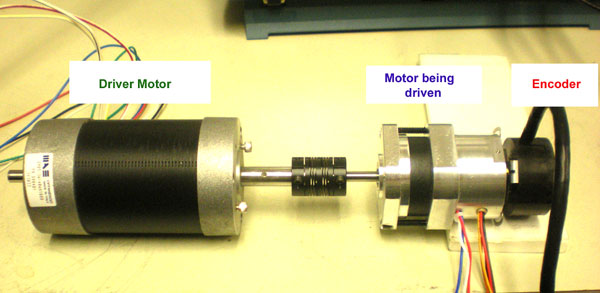
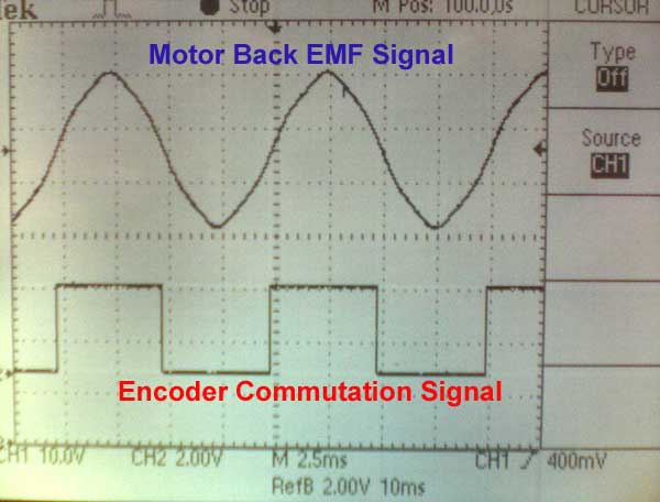
6) The motor/encoder is back driven by another motor and the two waveforms are displayed on an oscilloscope. One waveform is back EMF from the motor phase, and the other is the encoder commutation channel.

Back driven motor set up
Below the motor back EMF and encoder commutation (hall) signals are shown. They have been separated for clarity. When timing a motor you will want them to overlap.

7) While the motor is rotating, the assembly is fine tuned by rotating the incremental encoder body to align the encoder signal to the Motor waveform.
Video of BLDC motor back EMF to optical encoder hall phasing
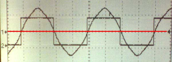
Proper timing typically calls for aligning the zero volt level of the back EMF sine wave with the edges of the commutation signals. That level is shown below by the red line.

8 ) Once alignment is achieved, the encoder flex mount is secured, locking in the phase relationship between the motor and encoder.
Contact Quantum Devices for More Information
Quantum Devices is dedicated to manufacturing high quality, high performance optical incremental rotary encoders for a multitude of industries. Our vertically-integrated manufacturing facility is located in Wisconsin, and all our products are made in the USA.


