Understanding Incremental Encoder Signals
June 29, 2014
Which Encoder Wires Should I Use to Begin Understanding Incremental Encoder Signals?
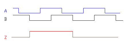
Channels A & B (Incremental Channels)
Use only A (or only B) for an RPM or counting applications where the rotation is either unidirectional, or where you don’t need to know direction.

Use A and B together to know direction. After two low pulses the next high pulse indicates direction. This is due to the phasing offset between A and B of 90 electrical degrees, placing the signals in what is known as quadrature.
These signals can also be used to set up an up/down counter

Index pulse, also known as Z, marker, or I
Index pulse is a pulse that occurs once per rotation. It’s duration is nominally one A (or B) electrical cycle, but can be gated to reduce the pulse width.
The Index (Z) pulse can be used to verify correct pulse count

The Incremental Encoder Index pulse is commonly used for precision homing. As an example, a lead screw may bring a carriage back to a limit switch. It is the nature of limit switches to close at relatively imprecise points. This only gives a coarse homing point. The machine can then rotate the lead screw until the Z pulse goes high.
For a 5000 line count incremental encoder this would mean locating position to within 1/5000 of a rotation or a precision of .072 Mechanical Degrees. This number would then be multiplied against lead screw travel.
Commutation (UVW) signals are used to commutate a brushless DC motor. I always like to compare these signals to that of a distributor in a car. The commutation (sometimes called “Hall”) signals tell the motor windings when to fire

You would need to have encoder commutation signals if the motor you are mounting the encoder to has a pole count and there is no other device doing the work of commutation. It is important to note that commutation signals need to be aligned or “timed” to the motor.
Single ended encoder wiring VS differential
These terms refer not to the waveforms of signals, but instead to the way the signals are wired.
Single ended wiring uses one signal wire per channel and all signals are referenced to a common ground.
TTL and Open Collector are types of single ended wiring.
Differential wiring uses two wires per channel that are referenced to each other. The signals on these wires are always 180 electrical degrees out of phase, or exact opposites. This wiring is useful for higher noise immunity, at the cost of having more electrical connections.
Differential wiring is often employed in longer wire runs as any noise picked up on the wiring is common mode rejected. RS-422 is an example of differential wiring.
Learn more about optical encoder wiring or send us an email for more information.
Buy rotary encoders online or contact Quantum Devices with any questions.
.

