Using an Optical Encoder to Show RPM on a PLC
April 27, 2014
.
I have interfaced a 200 line count QR145 optical encoder to a DL06 PLC. The PLC’s inputs are set up in high speed mode to receive the incremental quadrature pulses coming from the optical encoder.
.
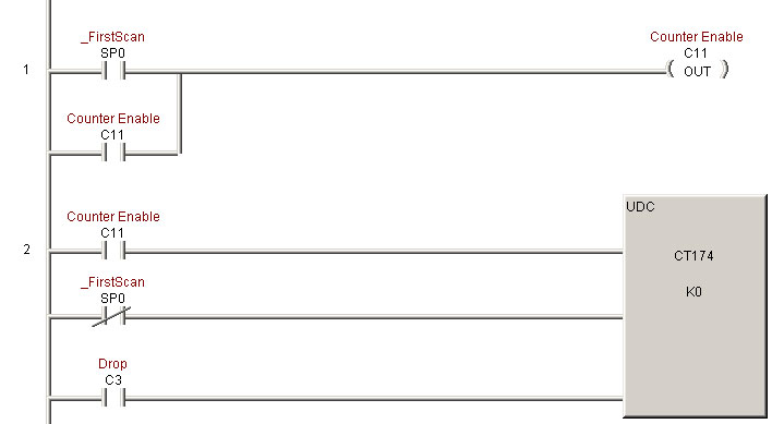
CT174, the designated high speed up/down counter is used to interface to the incremental encoder. By default, inputs X0 and X1 are used for the A& B incremental signals, without having to code them to the counter. Input X2 is designated as the reset, and may normally be connected to the index pulse of the encoder.
For an RPM application we will not be needing X2.

To calculate RPM with an optical rotary encoder we use this formula:
RPM = (Frequency X 60)/ Line Count
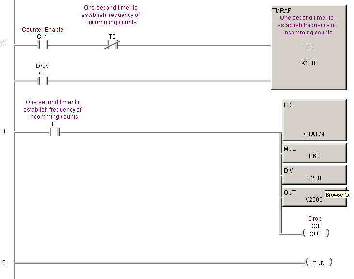
Since frequency is “cycles per second” we set up our high speed timer on rung three to give us a count total every second; this is our frequency.
Rung four is where all the heavy lifting happens:
After the high speed timer has timed out to one second, we load the PLC’c accumulator with the value from the counter (CT174). This will be our frequency, or the number of optical encoder counts that we have accumulated in one second.
We then multiply that value by 60, which uses our one second total to convert to the number of pulses occurring in a minute.
And we divide that total by 200, the line count, to get the RPM of the optical encoder.
We move the value to V2500, a location that we can pick up with the screen.
C3 is then used to reset the timer and counter and start the process over again.

.
.
Explore more incremental optical rotary encoders that can be used to find RPM, shop rotary encoders online, or contact Quantum Devices for help with optical encoders in your application.


