Using an Optical Encoder to Measure Angles
April 23, 2014
I have interfaced a 200 LC QR145 to a DL06 PLC to show how to convert from a line count to mechanical degrees. This type of conversion may be useful for any application of optical encoder to measure angles.
To calculate a degree measurement we divide 360 by the line count to get the number of degrees per pulse.
(360 Degrees /200 Pulses per revolution) = 1.8 Degrees per pulse.
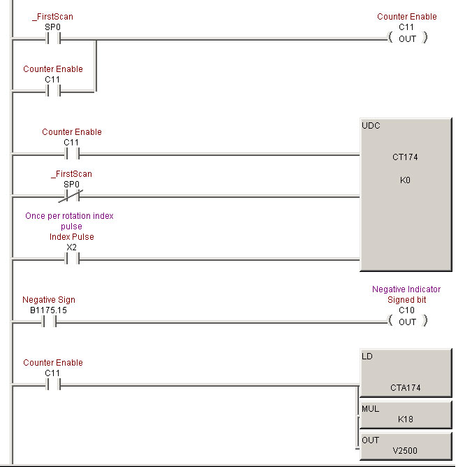
The High Speed counter we have set up will automatically add one to it’s running total any time the encoder is rotated counter-clockwise, and subtract one from the running total any time the optical encoder is rotated clockwise.
This value is loaded into the PLC’s accumulator and multiplied by 1.8 (K18) to convert to degrees. The number is then outputted to an address (V2500) that we can display on the screen.
When the index (Z) pulse occurs, we reset the counter to let it know we are back at zero.
Below is the PLC code for the pulses to degree conversion.

It is good to note that the PLC is set up to retain the count value when powered off, but if the optical encoder is rotated during this time, the count will not change and the value at power up will be different than the encoders real world position.
It is good practice to rotate an incremental encoder/optical encoder on power up until an index pulse is seen and start counting from there. This is technique is known as “homing”.
By default the quadrature counting mode within the PLC keeps track of negative numbers, so we are able to accumulate a negative degree value depending on the direction of rotation after zero. While this may seem a bit confusing, it is really just a matter of your point of reference. –90 Degrees is the same exact point as a positive 270 Degrees. If we wanted to convert to where we stayed within a positive degree range, you could change the PLC code to add 360 to the measured value any time it went negative.
For more information on encoders, contact Quantum Devices today.


