Optical Quadrature Encoders
February 22, 2014

Model QR145 optical quadrature encoder from Quantum Devices.
An optical quadrature encoder is an incremental encoder with outputs consisting of two incremental channels that are out of phase by 90 electrical degrees. In each part of the encoder cycle, the two signals are in unique positions relative to each other. By comparing the difference between the high and low points of each signal, speed and direction can be determined.
How Quadrature Encoders Work
A popular application for quadrature encoders is mounting them to an electric motor to track the speed and position of the motor shaft. Incremental optical encoders will often provide commutation “Hall signals” for timing of the BLDC windings, but in this case we’re looking at the incremental encoder channels, specifically A and B encoder channels.
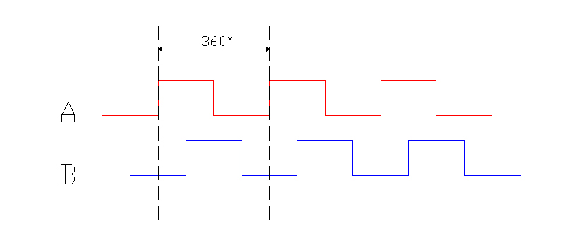
When using encoder incremental channels, their signals are in “quadrature”, where one channel is shifted by 90 electrical degrees from the other. Most people are familiar with mechanical degrees, and the idea that there are 360 of these in a circle. Electrical degrees are much along those lines in that there are 360 electrical degrees in each pulse encoder cycle. For an incremental optical quadrature encoder a cycle is the duration of one high and one low pulse as can be seen in the encoder pic below:

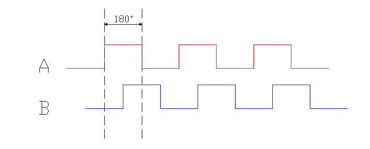
One of an encoder pulse (either High or low) is nominally 180 electrical degrees in duration, as seen below:

The edge separation for an optical quadrature encoder (motor encoder) between any two adjacent edges is ideally 90 electrical degrees. Since there are four 90 degree periods in a standard 360 electrical degree cycle, this amount of separation is referred to as being in quadrature.

Why set up the incremental optical encoder signals into quadrature? The reason is to give us rotational directional information. If we take either channel A or channel B and count how many of the pulses have occurred, it tells us how far we have gone in distance. If we were to compare that against a certain amount of time we can tell us how fast we are going (RPM for example), but it takes BOTH signals to tell us the direction in which the encoder shaft is rotating.
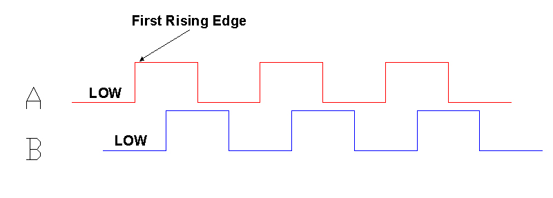
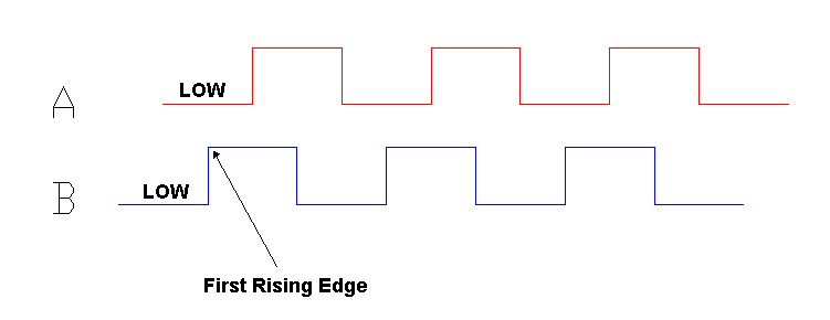
We are able to tell direction by finding which optical encoder channel transitions from low to high first. We do this by finding the point at which both signals are low, then look for the next rising edge.

If the shaft on the rotary encoder is spinning in the opposite direction the relationship between these two optical encoder channels is reversed.

There is a third encoder channel called the index pulse (aka Marker, I, or Z channel). We have a separate page dedicated to how index pulse gating works.
High-performance optical quadrature encoders
Quantum Devices designs and manufactures high quality optical quadrature encoders ideal for many different industries and applications:
Shop online in our encoder store, or get in touch to request a customized rotary encoder.

